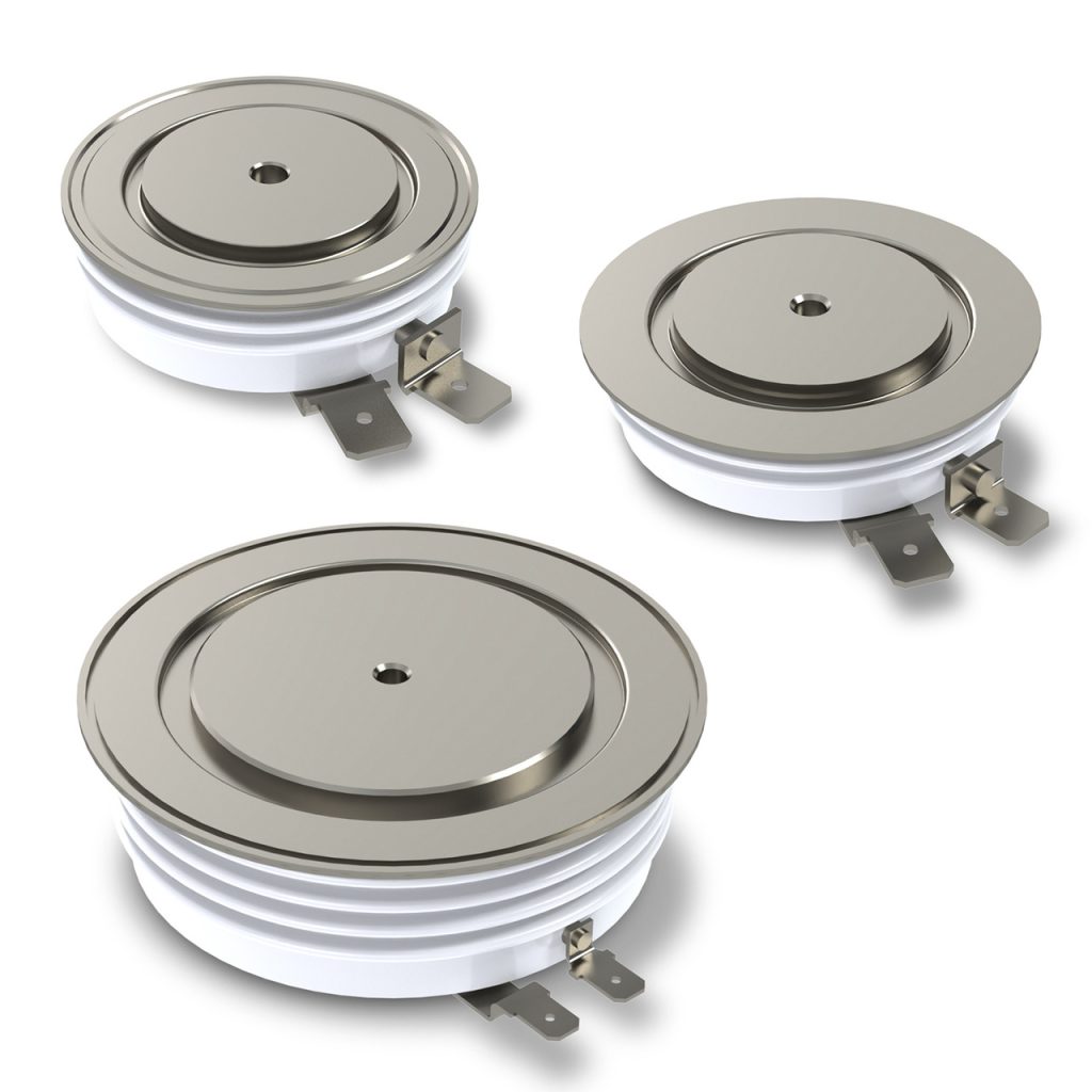
Nowadays there are many types of power semiconductor thyristors like phase control thyristors, fast and gate turn-off thyristors. Many companies produce these power semiconductor devices in various design featuring various characteristics and end applications. Today I would like to share with you the most popular types of thyristors available in power semiconductors market.
Thyristors for Industrial Frequency Applications (PCT)
These power semiconductor thyristors (also called phase control thyristors or PCT) are designed to work in equipment operating at a relatively low frequency – usually at an industrial frequency of 50 Hz or 60 Hz. These can be controlled rectifiers, soft-starters for electric motors, various inverters, etc. For these types of thyristors, the main attention is paid to minimizing power losses in the conductive state while providing a given forward and reverse blocking voltage.
Such thyristors are often used in converters, for voltages of 6-10 kV and higher, where a series connection of individual thyristors is necessary. Therefore, for such thyristors, it is quite relevant to increase the permissible blocking voltages, as well as to ensure synchronous switching-on and reverse recovery.
The values of Qrr and ЕRQ for a thyristor to be used at an industrial frequency can be very large, which, as a rule, excludes the possibility of their use at an increased frequency and in pulse-frequency modes. The turn-off time, as a rule, is more than 500 microseconds and is often not standardized by the manufacturers of power semiconductors.
Pulse Power Thyristors
These are the thyristors designed for switching current pulses with a high rate of rise at the front and a high amplitude.
Fast Thyristors
These are the power semiconductor thyristors with reduced values of tq, trr, Qrr, and ЕRQ designed for operation at high frequencies or in pulse-frequency modes. The characteristics of VTM, tq, Qrr, VRRM of a fast power semiconductor thyristor are connected with each other, i.e., the improvement of any of the listed characteristics leads to the deterioration of the rest.
To optimize the combination of VTM, tq, Qrr, VRRM, as in fast recovery diodes, technological methods are used that allow for a controlled reduction of the τ in the layers of the semiconductor structure: doping with heavy metal atoms (gold, platinum, etc.), irradiation with high-energy particles (γ-photons, electrons, protons, alpha particles, etc.). Sometimes methods to control the injection coefficient of the p-emitter are used. To reduce tq, a more efficient distributed cathode emitter shunting is also used with smaller distances between shunts compared with phase control thyristors.
Since operation at high frequencies is often accompanied by an increased speed at the front of the anode current pulses, fast power semiconductor thyristors are often subject to the requirements of pulse power thyristors – increased di/dt resistance and short turn-on time.
Light Triggered Thyristors (LTT)
A light triggered thyristor is a power semiconductor thyristor that is switched on in a contactless way. It is done not by a pulse of the gate current, but by a pulse of light.
The difference between the actual semiconductor structure is the absence of metal on the gate area of the auxiliary thyristor. Instead of the gate, a photodetector window is formed. The part of the collector p-n junction located under this window plays the role of a photocell and, when illuminated, generates a current that plays the role of the gate current. Light pulses are generated by a laser and delivered to the photodetector window via a fiber-optic cable.
Advantages of using light triggered thyristors with direct control of light pulses via a fiber-optic channel:
- Precise switching time control of a group of thyristors
- High-voltage galvanic isolation of the control circuit with the power circuit
- No influence of electromagnetic interference
- Compact arrangement of the fiber-optic cable in equipment
- Easy and safe maintenance of the equipment, long intervals between preventive maintenance
- Absence of mechanical wear of the elements
- Reduction of the number of elements in the scheme
- High efficiency and reliability of thyristors and the circuit in general
The advantages listed above are of the greatest importance for high-voltage series connection power semiconductor thyristor assemblies, where the development of equipment using light triggered thyristors is widely spread nowadays.
Gate Turn-off Thyristors (GTO)
The main functional disadvantage of a conventional power semiconductor thyristor as a switch of power electronics is its incomplete controllability: the thyristor can be switched on by a signal (pulse of the gate current) along the control circuit, but to turn it off, an interruption or a change of polarity of the power anode current is necessary for a certain period of time – turn-off time.
The presence of this disadvantage prevents the effective use of conventional thyristors in a number of power electronics applications that require the use of fully controlled switches, i.e., power semiconductors, in which both switching on and off can be carried out by a signal through the control circuit.
The gate turn-off thyristor or GTO is a fully controlled modification of the thyristor. Both switching on and off of this power semiconductor device can be done by a current pulse in the control circuit.
A conventional thyristor cannot be switched off by a gate current pulse, since the area where the gate current plays a role in the overall balance flow of electrons and holes in the thyristor layers is limited by a narrow band adjacent to the edge of the p-type control region.
In the gate turn-off thyristor, the width of each elementary thyristor is small, i.e., the band adjacent to the edge of the control area occupies the entire area of each elementary thyristor.
Therefore, if a reverse polarity gate current is applied to the switched-on turn-off thyristor (GTO), then it is possible to create such conditions when the sum of the current gain coefficients of the constituent transistors becomes less than 1, the collector p-n junction will come out of saturation, i.e., the thyristor will turn off.
The width of the cathode cells is thus selected from the condition of reliable turn-off of all elementary thyristors by the turn-off gate current. The length of the cells is selected from the condition of the most efficient use of the area of the rectifier element.
The amplitude of the switching current pulse in the GTO control circuit is comparable in order of magnitude with the anode current – the turn-off coefficient (the ratio of the value of the “turn-off” anode current to the value of the “turn-off” current in the control circuit) does not exceed 3-4.
Gate Commutated Thyristors (GCT)
In the middle of the ’90s, a number of leading semiconductor manufacturers developed a new generation of gate turn-off thyristors – GTOs with hard switching.
These power semiconductor devices include:
- GCT (Gate Commutated Thyristor) is a GTO with hard switching, without a driver
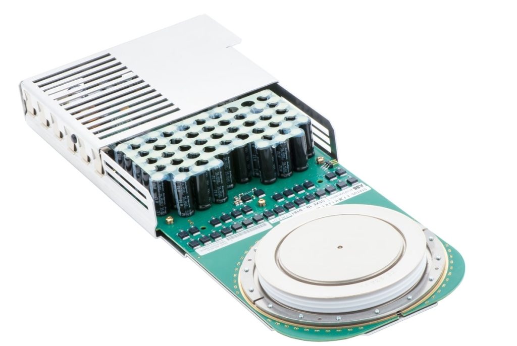
- IGCT (Integrated Gate Commutated Thyristor) is a GCT integrated with a driver
- ETO (Emitter Turn-Off Thyristor) or ECT (Emitter Controlled Thyristor) is a GCT integrated with a driver and switched via a cascade circuit.
All these power semiconductor devices have the same design of the rectifier elements. The only difference is that the width of the discrete cathode emitter cells of the rectifier element of these devices is smaller and lies in the range of 100-200 microns, i.e., the rectifier element of these power semiconductor devices has a thinner topology.
A significant disadvantage of the integrated gate commutated thyristors (IGCT) is the bipolar nature of its control. To quickly and safely switch on and off the device, current pulses with an amplitude of several thousand amperes must be passed through its control circuit. On the other hand, to maintain the turn-on state of the IGCT at a low value of the anode current (a situation typical to the operation of the switch in the power supply system of an asynchronous electric motor), a recharge is required along the current control circuit up to several amperes.
All this leads to the need to power the integrated gate commutated thyristor (IGCT) driver from a source of the considerable power of 200-500 W, which is not always feasible, especially with increased requirements for weight, size, and equipment efficiency.


